6' x 4' Wooden Sider Trailer
Drawbar Setup
Fitting the Drawbar
Lay the two drawbar sections down the centre of the trailer parallel with the chassis rails with the long edge vertical. Take one section and slide the inside end around till the inside edge is resting against the inside upright of the spring hanger and tack weld in position.
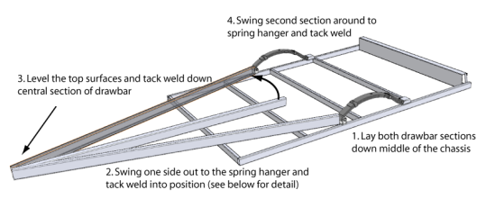
Repeat with the second section and then take the protruding sections and work them gently until the inside edges are together and tack weld. At this point it is a good idea to double check that the drawbar is central and to do this take a couple of measurements from the same point on the drawbar diagonally back to a point on the chassis in a couple of positions and check that both measurements from each side match. If not, you will need to recheck the position of the spring hangers and the lengths of the drawbar sections. If necessary, reposition the hangers or grind the drawbar to suit.
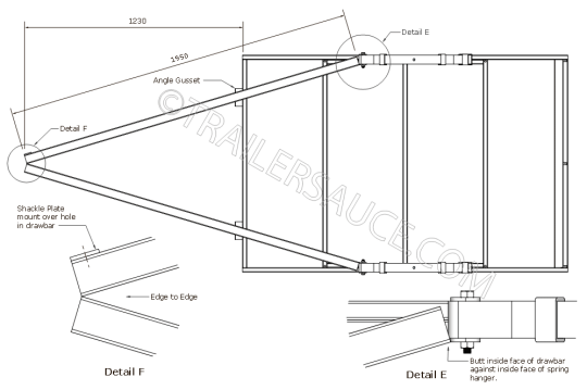
Centralise the angle gusset under each section of the drawbar, against the front crossmember. Tack weld into position.
At this point you can weld up the drawbar in all the downhand and vertical positions. Do not under any circumstances weld across the horizontal faces on the drawbar where it intersects the crossmembers, or the front edge of the angle gussets as shown below.
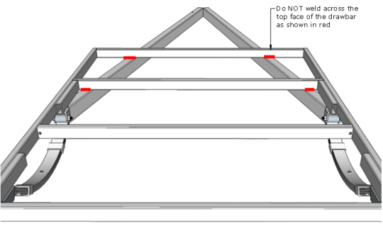
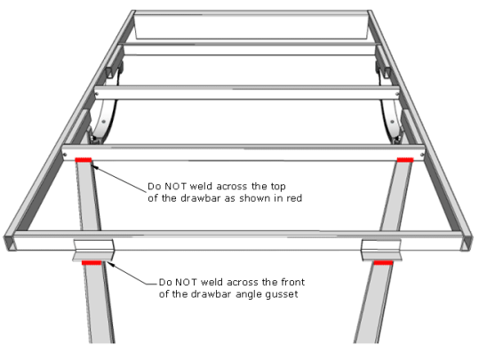
Note - The reason for not welding the top face of the drawbar and most importantly across the front of the angle gusset is that when steel is welded, the heat from welding process alters the crystalline structure of the steel and creates a "heat affected zone" or HAZ. This HAZ is generally weaker and prone to cracking depending on the circumstances the welded section is placed under.
The drawbar does a lot of work while towing. Every little bump in the road and every turn you make transfers stress through the drawbar and compresses, twists and stretches the drawbar material constantly. The majority of this flexing occurs where the chassis and drawbar are connected and is enhanced when the trailer is constantly overloaded or unbalanced. This repeated loading and unloading (cycling) of stresses on the drawbar can create microscopic cracks within the grain structure of the drawbar material especially around the HAZ.
Fitting an angle gusset over the drawbar top face gives addition area for supporting the load placed on the drawbar and reduces the potential for drawbar failure.
For more information on drawbar design click here.
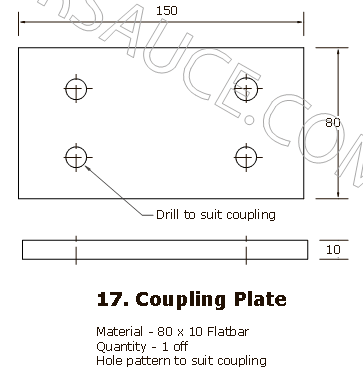
Coupling Plate
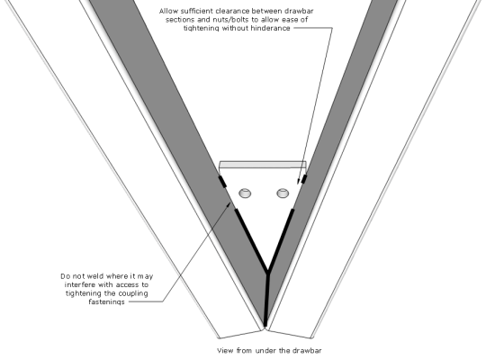
Drill the coupling plate to suit your coupling hole setup (adjust the plate size if required) and fit to the front end of the drawbar in a position that allows easy access for tightening nuts and bolts from within the drawbar section (drill holes thru top of drawbar to match coupling plate) and from between the vee of the drawbar,
If you are using a lever style coupling, ensure there is adequate overhang from the front of the coupling plate to prevent jamming of the coupling tongue when the lever is lifted.
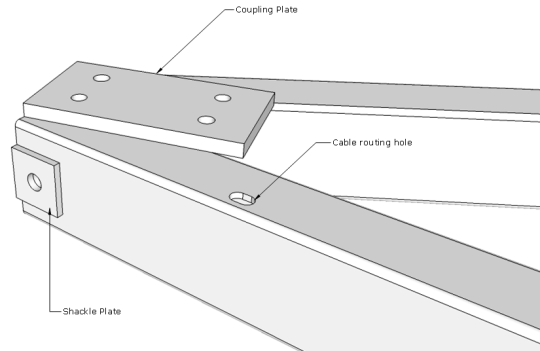
Fully weld the coupling plate to the drawbar sections ensuring good penetration of the coupling plate. If room is tight for adequate access to the fastenings in the vee section (underside), mark where access is required and refrain from welding at these points.